Roof Level Cut Plane Revit

Solved Can T Seem To Changing The Cut Plane In The View Range Autodesk Community Revit Products

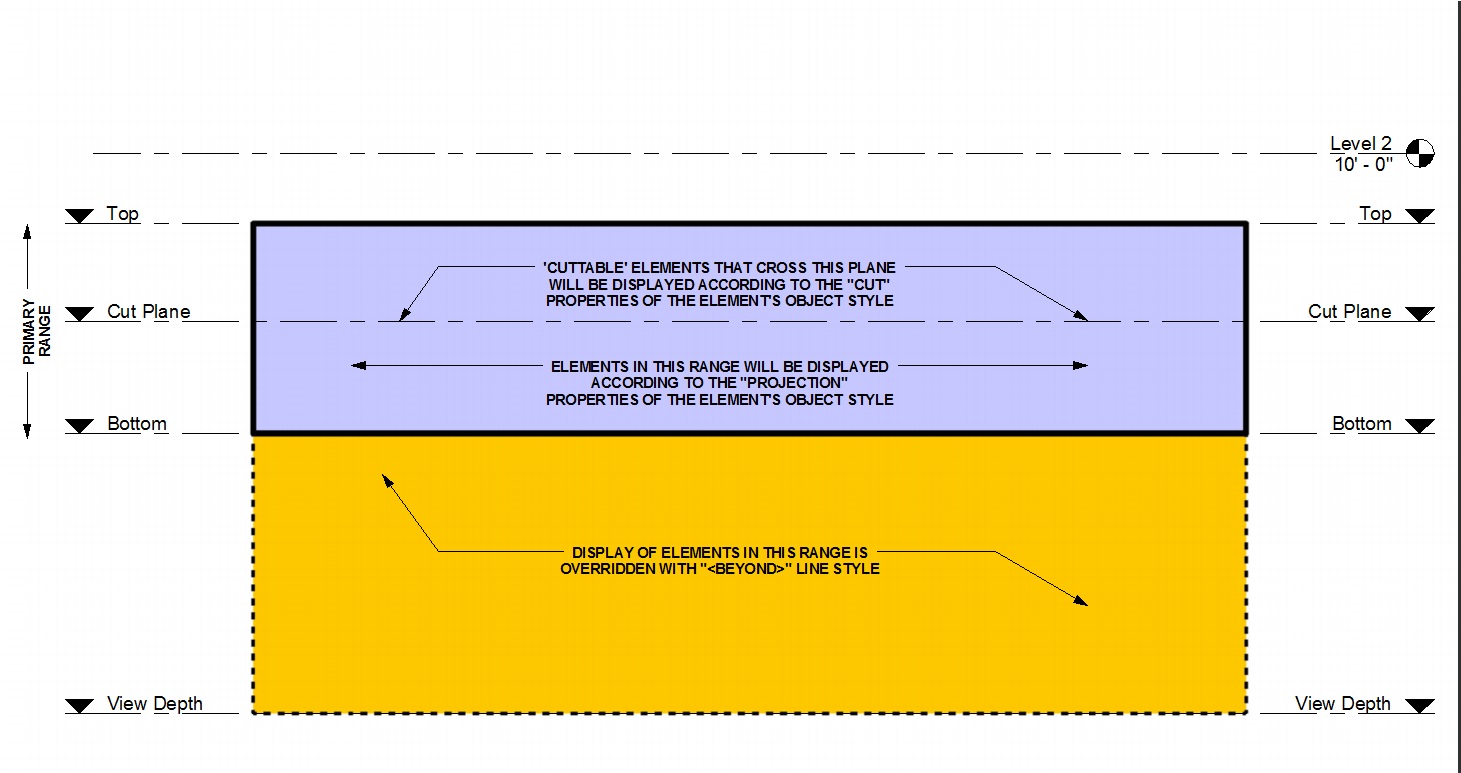
How To Use View Range In Revit Revit Pure
Roof View Range Autodesk Community Revit Products

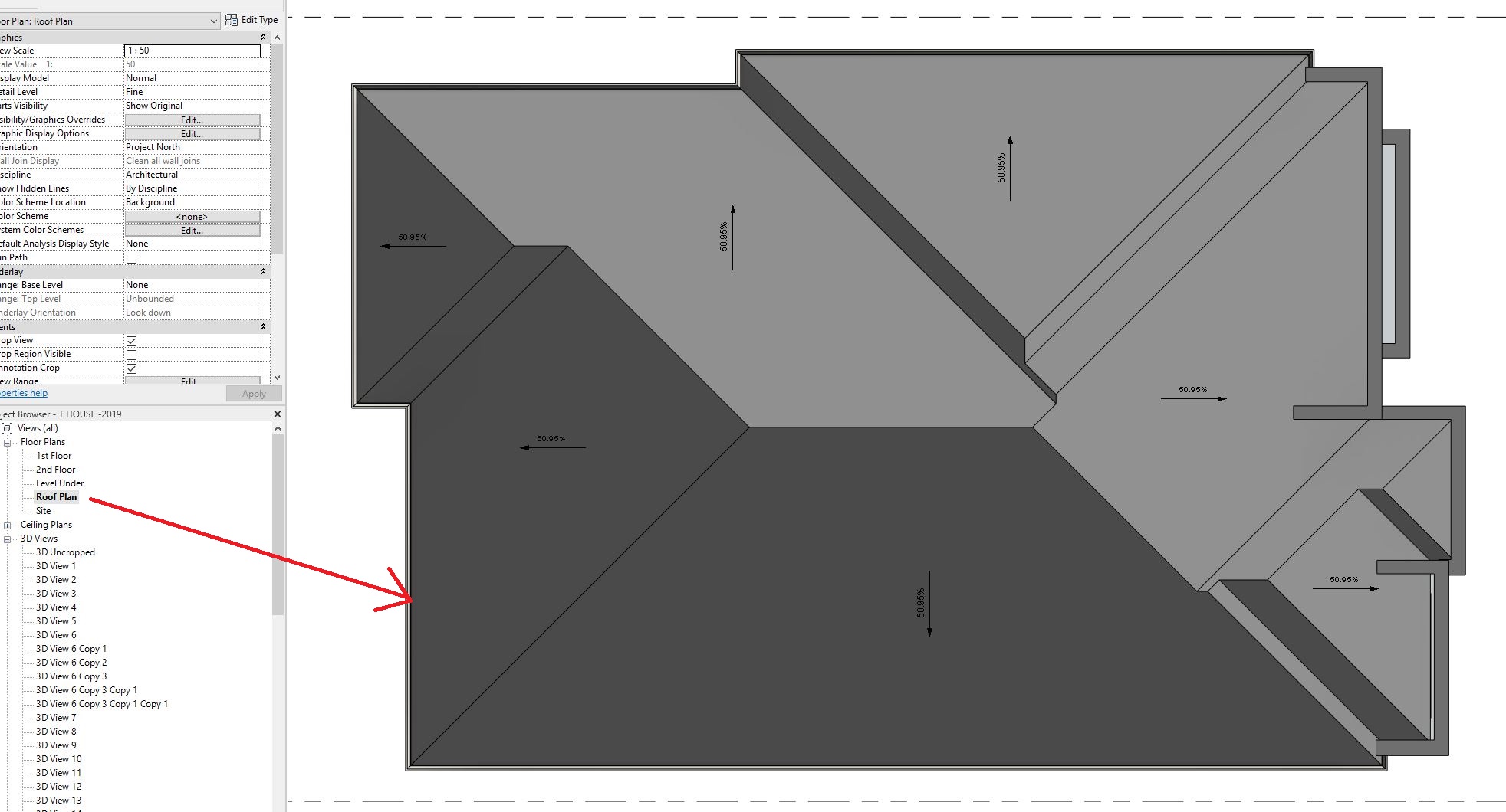
Solved Roof Plan Questions Autodesk Community Revit Products

Solved See Beam Grid Along Roof On Each Level Autodesk Community Revit Products

View Range Revit Products Autodesk Knowledge Network

Top cut plane and bottom.
Roof level cut plane revit.
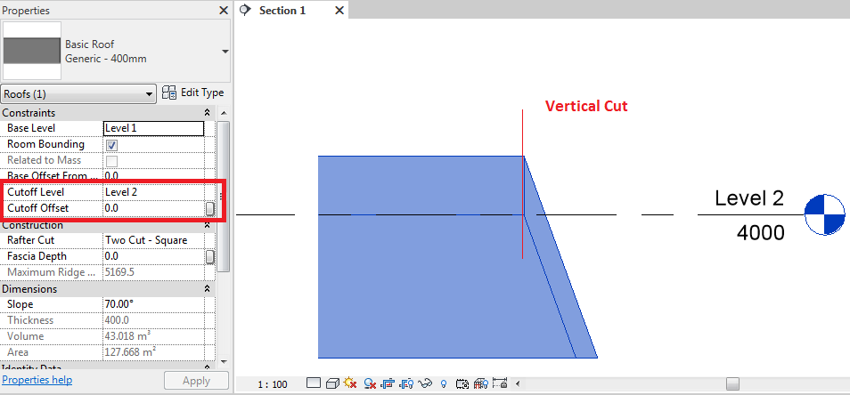
Cutoff Level Roof Behavior In Revit Revit Products 2018 Autodesk Knowledge Network
Why A Floor Plan S View Range Is Illogical And Puts Off New Users Autodesk Community Revit Products

Trim Wall Top With Ref Plane Autodesk Community Revit Products

Solved Specific Levels In View Range Autodesk Community Revit Products

Cut Section To Display Crop Region At Level It Is Cut From Autodesk Community
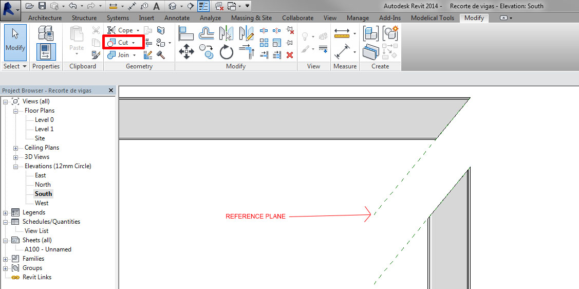
Cut Beams And Columns In Revit Modelical

New Level Missing Plan View Autodesk Community Revit Products

View Range Settings In Revit Tutorial Youtube
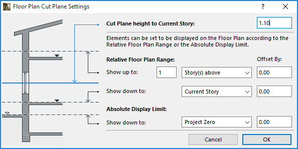
Floor Plan Cut Plane Settings Dialog Box User Guide Page Graphisoft Help Center

Solved Problem View Level With Inclined Floor Autodesk Community Revit Products
Https Static Sdcpublications Com Pdfsample 978 1 58503 885 5 7 Pdf
Solved Objects Outside Of View Range Still Visible Autodesk Community Revit Products

Solved Roof Window Not Being Cut In Plan View Autodesk Community Revit Products

Solved What Floor Plan Does A Roof Get Drawn On First Or Second Autodesk Community Revit Products

Tutorial Bka Blog Studio Bka

Solved Cannot Select Roof Edge Autodesk Community

Revit Tutorials 8020 Bim

Revit Roof Basics 10 Slope Arrow Cadclips Youtube
Https Encrypted Tbn0 Gstatic Com Images Q Tbn 3aand9gcskbk87qailjhvhniaq7hczgcxnxljk9gfyx Px1dlgzhqjllwt Usqp Cau

Floor Plan Visibility Autodesk Community Revit Products

Solved Display Window Above Cut Plane Autodesk Community Revit Products

Solved Wall Visibility Through Roof Autodesk Community Revit Products
Cut Behavior Of Low Walls The Revit Clinic

Roof Cutoff Level Youtube
Source : pinterest.com
